26+ motor driver block diagram
All other devices on this design receive power from the 12-V battery. The L6472 device realized in analog mixed signal technology is an advanced fully integrated solution suitable for driving two-phase bipolar stepper motors with microstepping.

Brushless Dc Motor Control With Arduino And L6234 Driver Simple Projects Arduino Electronics Circuit Electronic Circuit Design
Working of Stepper Motor.
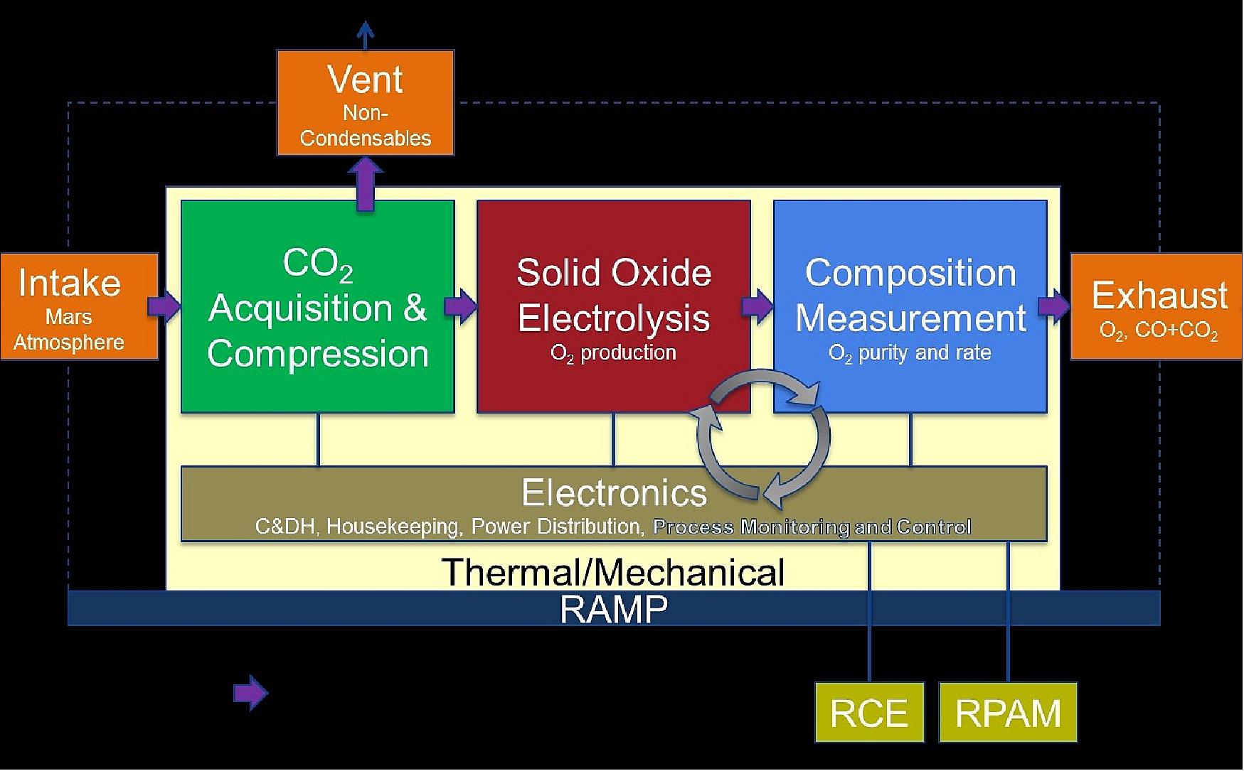
. As shown in Figure1 it is the block diagram of hybrid control solar tracking system and it is the structure diagram of hybrid control solar tracking system in Figure2. In brief the SLG47105 is used as a driver for the stepper motor. The motor drive design uses the 48-V battery only to drive the motor and is isolated from the 12 -V battery.
Generally stepper motors are operated by electronic circuits mostly on a dc power supply. The RM4 and TMS570 Hercules Safety MCUs are based on the widely used ARM Cortex R4F core and are built to ease the development and certification of safety critical. The block diagram of an electric drive is shown below and the load in the diagram signifies different kinds of equipment which can be built with an electric motor such as washing.
In this design example the driver has two modes. Brushless DC Motor Driver - 24 volt Block Diagram LDO 12V TO 33VMIC523 MIC4682YM Step-Down Regulator 24V DC in KEYBOARD Functions Part Number Units Description. Stepper motor working principle.
Full step and 116 step. 3 MCU controller system. This system is designed with an.
The MCU controls the driver. To decouple the inner current loop from the machine-inherent induced emf loop it is necessary to split the transfer function between the speed and voltage into two cascade transfer functions. Functional Diagram Each Driver FN28537 FN28537 Dual Power MOSFET Driver The ICL7667 is a dual monolithic high-speed driver designed to convert TTL level signals into high current.
The function of the motor drive is to draw electrical energy from the electrical source and supply electrical energy to the motor such that the desired mechanical output is achieved. An electrical drive can be defined as a system that can be used to handle the movement of electrical machines like motors or generators.

Drs Catalog Pdf 13 6mb Demag Cranes Amp Components
2

Brushless Dc Motor Driver Circuit Diagram Circuit Diagram Electrical Circuit Diagram Motor

Pin On Schematic
Mars Perseverance

Schematic Of The Ac Motor Controller Motor Speed Circuit Diagram Motor
How Will U Differentiate A Plc And An Embedded System Quora
2

12 Volt Dc Motor Speed Controller Motor Speed Circuit Diagram Electronic Circuit Projects
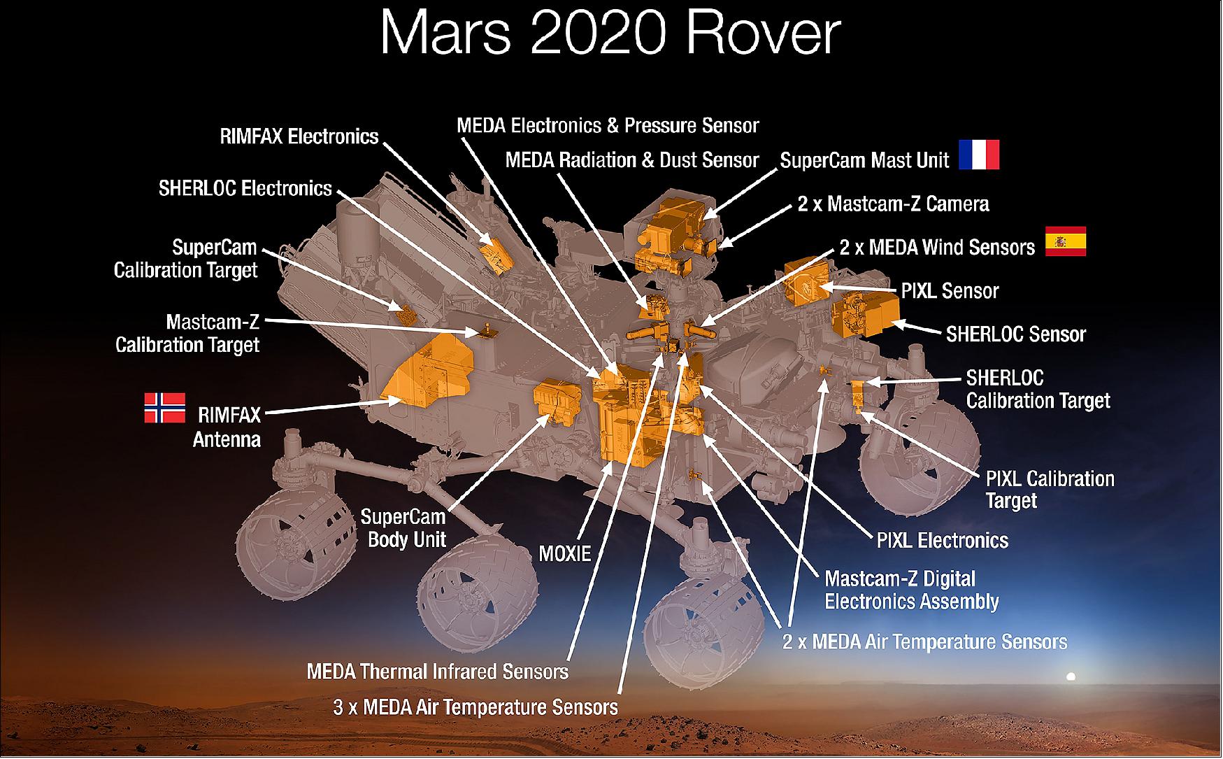
Mars Perseverance
2

Dc Motor Speed Control Using Microcontroller Pic 16f877a Projects Motor Speed Microcontrollers
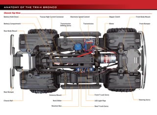
Trx Car Toturial
2

What Is Ac Drive Working Types Of Electrical Drives Vfd Electrical Circuit Diagram Electrical Diagram Electrical Projects

Nova Spot Micro 3 A Spot Mini Clone Quadruped Robot Dog 7 Steps With Pictures Instructables
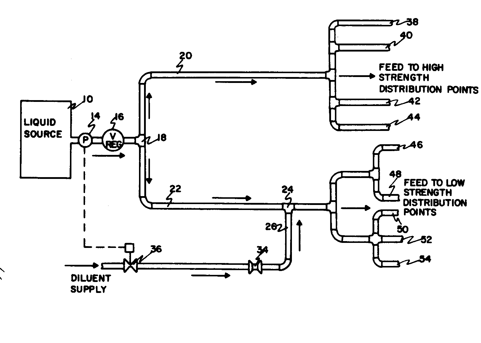
Class Definition For Class 137 Fluid Handling